ABSTRACT
Polymer nanocomposites incorporating inorganic nanofillers have emerged as highly promising electromagnetic interference (EMI) shielding materials, combining mechanical compliance with robust conductive percolation networks. Carbon nanotubes (CNTs) are particularly attractive as conductive fillers because their high aspect ratio facilitates percolation at low loadings. Also, CNTs offer superior mechanical durability under deformation compared to rigid, fracture-prone metal nanowires. For EMI shielding, high electrical conductivity is critical as it enhances both reflection and absorption through efficient charge dissipation and conduction losses. However, achieving highly aligned conductive pathways without degrading the intrinsic electrical properties of CNTs remains a significant challenge. Here, we demonstrate a non-destructive magnetic surface-functionalization and alignment strategy. Using a polydopamine (PDA)-mediated route, pristine multiwalled CNTs are uniformly decorated with Fe3O4 nanoparticles (FMWCNTs). This enables highly effective magnetic field-driven alignment at fields as low as 10 mT, promoting the strategic formation of percolation networks. By optimizing the Fe₃O₄/MWCNT ratio for high saturation magnetization and uniform coverage, the aligned FMWCNTs exhibit significant electrical anisotropy, delivering a 10.7-fold higher electrical conductivity in the parallel configuration compared to the vertical configuration. These findings present a scalable, room-temperature platform for engineering directionally enhanced conductivity in polymer nanocomposites, with broad applicability in advanced EMI shielding, flexible electronics, and advanced packaging technologies.
-
KEYWORDS: Magnetic alignment, Multiwalled carbon nanotubes, Fe3O4 nanoparticles, Polymer nanocomposites, Percolation
Electromagnetic interference (EMI) shielding can be achieved through diverse material platforms and mechanisms, ranging from bulk metals and conductive coatings to multilayer structures [
1]. Among these approaches, polymer composites incorporating inorganic fillers have emerged as a highly attractive strategy. By introducing electrically conductive fillers into polymer matrices, these composites enhance EMI shielding through combined reflection and absorption associated with conduction loss, interfacial polarization, and magnetic/dielectric losses. Importantly, they offer lightweight, mechanically compliant form factors that surpass conventional metallic shields. Their shielding performance can be readily modified by controlling filler composition, morphology, and dispersion. In addition, they enable scalable and corrosion-resistant manufacturing that is compatible with complex geometries and large-area processing. The incorporation of even a small fraction of functional inorganic nanofillers allows these composites to form electrically conductive pathways, which is essential for the development of integrated structural and functional components for wearable electronics, soft robotics, and advanced packaging. The formation of such continuous pathways is described by percolation theory, where conductivity rises sharply once an interconnected filler network spans the matrix. Carbon nanotubes (CNTs) are particularly attractive fillers because their high aspect ratio facilitates percolation network formation at relatively low loadings. In addition, CNTs can be applied for polymer processing while simultaneously providing high conductivity and mechanical reinforcement [
2]. Moreover, unlike rigid metal nanowires that can fracture under deformation, CNTs maintain superior mechanical durability in polymer matrices.
Despite these advantages, achieving high conductivity at ultralow CNT content remains a significant challenge. It requires not only homogeneous dispersion to prevent massive agglomeration but also the strategic formation of a continuous, highly efficient conductive network throughout the nanocomposite. Therefore, constructing tailored filler architectures at minimized loadings is critical, as excessive CNT loading can deteriorate processability and induce stress concentration, ultimately leading to premature mechanical failure. Several routes have been explored to achieve CNT alignment within polymer matrices. In particular, shear and drawing can induce partial alignment. However, the attainable orientation is often modest for high-aspect-ratio CNTs and is strongly influenced by matrix rheology and processing conditions [
3]. Electric-field alignment can also produce well-oriented CNT assemblies to enhance electrical conductivity [
4]. However, the requirement for closely spaced conductive electrodes largely limits this approach to thin or planar geometries, and residual charges can trigger CNT aggregation during or after processing [
5]. By contrast, magnetic field-driven alignment offers a highly advantageous noncontact approach, avoiding the electrode-induced electrochemical reactions common in electrically assisted alignment [
5].
In this context, magnetic field-induced chaining and the directed assembly of fillers have been shown to significantly reduce the percolation threshold. Unlike purely geometric alignment, which can decrease intersection probability, magnetic dipole interactions facilitate tip-to-tip connectivity, increasing the probability of forming a continuous conductive pathway at reduced filler contents [
2]. In randomly oriented CNT networks, charge transport is often limited by nanotube–nanotube junctions that contribute appreciable contact resistance. Aligning CNTs along a preferred axis increases the fraction of continuous conduction paths and decreases the number of resistive junctions, leading to substantially enhanced conductivity along the alignment axis—achieving up to a 360% enhancement compared to randomly dispersed networks [
3]. However, effective magnetic alignment in a polymer solution requires a magnetic torque sufficient to overcome viscous resistance. This presents a significant challenge for diamagnetic fillers, including pristine CNTs, which typically require impractically high magnetic fields on the order of 9.4 T to achieve alignment [
4]. To reduce this required field strength, CNTs have been decorated with magnetic nanoparticles to enhance magnetic susceptibility, enabling orientation under much lower fields (~50 mT) [
5]. For instance, Correa-Duarte et al. reported that multiwalled CNTs (MWCNTs) coated with magnetite/maghemite nanoparticles could be aligned at room temperature under 0.2 T, a flux density easily accessible using permanent magnets [
6]. Subsequent studies further demonstrated that polymer composites containing these magnetically decorated CNTs exhibit strong anisotropic electrical conductivity [
7].
Despite these advances, achieving uniform nanoparticle decoration while preserving the intrinsic electrical properties of CNTs remains a critical bottleneck. Previous studies typically require prior surface functionalization to create anchoring sites for nanoparticle nucleation or binding [
8]. These functionalization methods frequently employ strong oxidizing acids, which generate defects in the graphitic lattice and disrupt the π-conjugated network essential for efficient charge transport [
9]. To address this defect formation while ensuring robust nanoparticle anchoring, polymer-assisted surface modifications using amphiphilic or adhesive interlayers have been explored [
10]. Among these, polydopamine (PDA) offers a highly effective way for CNT surface functionalization while completely avoiding harsh acid treatments. Under mild alkaline conditions, dopamine undergoes self-polymerization, and the resulting PDA adheres to diverse substrates via catechol-mediated interactions and π–π stacking [
11]. Because this room-temperature coating proceeds primarily via non-covalent interactions, it minimizes the disruption of the CNT sp2 carbon framework [
12]. Furthermore, the resulting PDA layer introduces catechol and amine functional groups that enhance interfacial binding with metal oxide nanoparticles via metal-catechol coordination [
13], thereby enabling uniform nanoparticle decoration without relying on destructive acid treatments [
14].
In this work, we demonstrate a non-destructive, PDA-mediated surface functionalization strategy to uniformly deposit Fe₃O₄ nanoparticles onto MWCNTs, without the need for harsh acidic pre-treatments. By systematically optimizing the PDA coating conditions and Fe₃O₄ loading, we achieve highly efficient percolation networks driven by magnetic field-induced alignment, substantially preserving the intrinsic electrical properties and structural integrity of the CNTs.
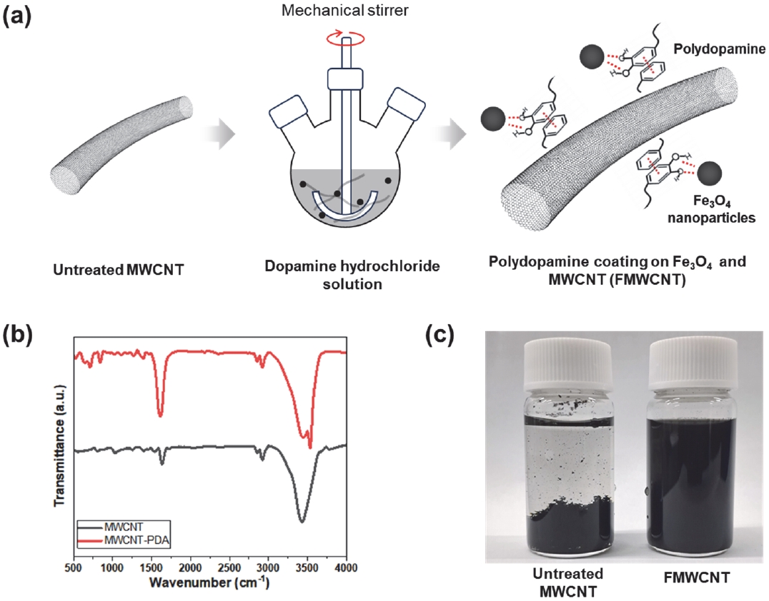
Figure 1(a) illustrates the synthetic procedures for the PDA-mediated Fe₃O₄/MWCNT (FMWCNT) nanocomposites via an oxidative polymerization method. First, Fe
3O
4 nanoparticles were synthesized through a solvothermal method as described in a previous study [
15]. In detail, 4 mmol of ferric chloride hexahydrate (FeCl
3·6H
2O) was mixed with 10 mL of ethylenediamine (EDA) under vigorous magnetic stirring. Then, 20 mL of ethylene glycol (EG) was added to the solution. The mixture was stirred vigorously for 1 h and subsequently sealed in a 50 mL Teflon-lined stainless-steel autoclave. The autoclave was maintained at 200°C for 12 h with a heating rate of 2°C/min, and then naturally cooled to room temperature. The resulting black solid product was collected by rinsing with ethanol several times. To synthesize the FMWCNT nanocomposites, 10 mg of MWCNTs and calculated amounts of Fe
3O
4 nanoparticles were co-dispersed in 35 mL of an ethanol/water (4:3 v/v) mixture by bath sonication for 30 min to achieve specific Fe
3O
4-to-MWCNT weight ratios (e.g., 5, 10, and 15). Following sonication, 40 mg of dopamine hydrochloride and 10 mL of 25 mM Tris-HCl buffer (pH 8.5) were added under mechanical stirring. The mixture was stirred for 24 h at room temperature to facilitate the self-polymerization of dopamine. Finally, the product was separated by centrifugation, washed thoroughly with deionized (DI) water, and dried at 50°C in a vacuum oven.
Figure 1(b) displays the FTIR spectra of the as-prepared FMWCNTs compared with pristine MWCNTs. Compared to the pristine MWCNTs, a broad band near 3,400 cm
-1 was observed for the FMWCNTs. This is attributed to the O-H and N-H stretching vibrations from the catechol hydroxyl and amine groups in the PDA [
16]. The peaks at 1,620 cm
-1 and 1,590 cm
-1 exhibit aromatic C=C stretching vibrations induced by the indole/quinone ring structures. Additionally, N-H bending and C-N stretching vibrations from the indole group of the PDA were observed at 1,510 cm
-1 [
16]. This FTIR spectral analysis confirms the successful PDA coating on the MWCNT surface, consistent with the fabrication procedure outlined in
Fig. 1(a).
To investigate the dispersion behavior of the nanocomposites based on their surface properties, both pristine MWCNTs and FMWCNTs were dispersed in DI water (
Fig. 1(c)). Pristine MWCNTs showed poor dispersibility in DI water because of their intrinsically hydrophobic surface. In contrast, the PDA-mediated FMWCNTs exhibited markedly improved aqueous dispersion, as the PDA layer introduced hydrophilic catechol and amine functionalities that increased surface wettability. Notably, the FMWCNTs maintained excellent dispersion stability for over 7 days after sonication, remaining stably dispersed in the hydrophilic solvent.
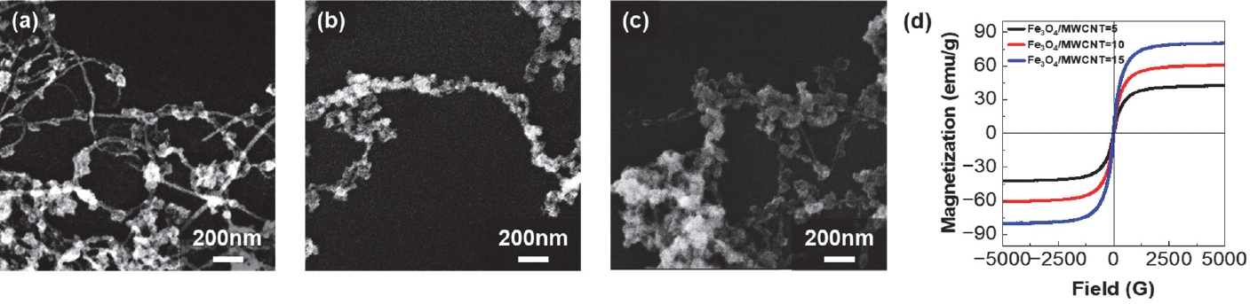
Scanning electron microscopy (SEM) images of the synthesized FMWCNTs with varying Fe₃O₄/MWCNT weight ratios are shown in
Figs. 2(a-c). At a Fe
3O
4/MWCNT weight ratio of 5, insufficient decoration of Fe
3O
4 nanoparticles on the surface of the MWCNTs was observed. However, when the weight ratio of Fe
3O
4 to MWCNT exceeded 15, excessive decoration of nanoparticles was observed, leading to severe agglomeration. The electrical conductivity of the FMWCNTs reflects a critical trade-off between the Fe
3O
4 loading and the continuity of the MWCNT percolation network. Since Fe
3O
4 is a metal oxide with relatively low electrical conductivity (10⁻⁴–10⁻² S/m), whereas MWCNTs exhibit much higher conductivity (~10⁵ S/m), the Fe
3O
4/MWCNT weight ratio strongly influences overall charge transport [
17]. As the Fe
3O
4 fraction increases, the electrical conductivity decreases because the Fe
3O
4 nanoparticles partially mask the surface of the CNTs and reduce direct electrical contacts within the conductive network. Furthermore, at elevated Fe
3O
4 loadings, nanoparticle agglomeration decreases the accessible CNT surface area and increases inter-tube junction resistance, further lowering conductivity [
4]. As shown in
Fig. 2(c), a high Fe
3O
4/MWCNT weight ratio yields extensive nanoparticle coverage with dense surface packing. This morphology inherently obstructs the formation of an efficient percolation network, because a large fraction of the agglomerated Fe
3O
4 nanoparticles block the conductive pathways between the CNTs. Therefore, optimizing the Fe
3O
4/MWCNT weight ratio is critical to achieving a uniform magnetic particle coating while preserving the high intrinsic conductivity of the CNTs. The magnetic properties of the FMWCNTs with varying weight ratios were investigated using vibrating sample magnetometer (VSM) analysis (
Fig. 2(d)). As the weight ratio of Fe
3O
4 to MWCNT increased, the saturation magnetization increased from 42 emu/g to 80 emu/g, which is consistent with the higher fraction of magnetic nanoparticles. A higher saturation magnetization is expected to increase the magnetic torque acting on the hybrids under an applied field, thereby facilitating highly efficient magnetic alignment [
6]. Consequently, an optimal Fe₃O₄/MWCNT weight ratio of 10 was chosen for the subsequent alignment studies. This specific composition exhibited high saturation magnetization while seamlessly maintaining uniform, well-dispersed nanoparticle coverage on the CNT surface without critical agglomeration.
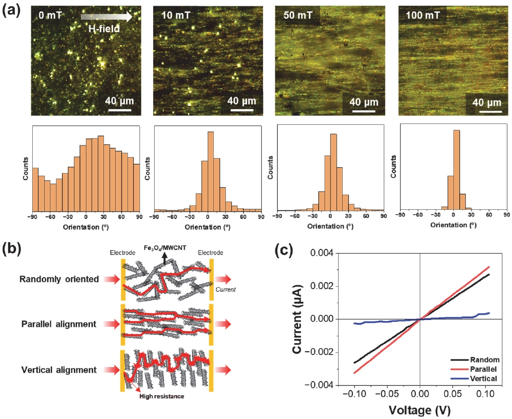
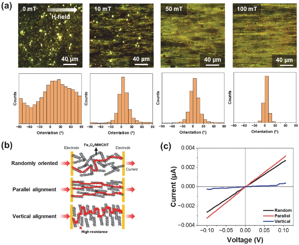
Figure 3 illustrates the alignment characteristics of the FMWCNTs under an external magnetic field.
Figure 3(a) shows dark-field optical microscopy (OM) images of 0.5 wt% of FMWCNTs in a PDMS matrix at magnetic field strengths of 0, 10, 50, and 100 mT, along with their corresponding angular distribution histograms. PDMS was chosen as a model elastomer matrix because it is readily processable and optically transparent, enabling the direct visualization of magnetic field-driven filler alignment while representing a compliant polymer platform for composite coating applications. In the absence of an external magnetic field, the FMWCNTs are randomly dispersed with a broad angular distribution, indicating no preferential orientation. At 10 mT, a preferential angular distribution begins to emerge, suggesting the onset of alignment along the field direction. At 50 mT, the FMWCNTs show clear alignment parallel to the applied magnetic field, and at 100 mT, nearly all FMWCNTs are oriented uniaxially, as seen in the sharp, narrow histogram peak. These results confirm that the Fe
3O
4 nanoparticles decorated on the outer walls of the MWCNTs provide sufficient magnetic anisotropy to drive effective alignment at magnetic fields as low as 10 mT.
Figure 3(b) schematically shows how FMWCNT orientation affects electrical percolation pathways between two planar electrodes. When FMWCNTs are randomly dispersed, conduction pathways form only through occasional contacts, limiting overall charge transport. In contrast, when FMWCNTs are aligned parallel to the current flow, enhanced end-to-end connection and inter-tube contacts between neighboring nanotubes build a denser percolation network, resulting in more continuous conduction pathways and lower resistance. When FMWCNTs are oriented vertical to the measurement axis, these continuous longitudinal contacts are largely disrupted, severely reducing the number of effective percolation paths and leading to higher resistance compared to the parallel configuration.
Figure 3(c) shows the corresponding current–voltage (I–V) characteristics for both configurations of the 0.5 wt% FMWCNT/PDMS nanocomposites. I–V measurements were performed in a planar two-electrode geometry using two copper electrodes (15 mm × 2.5 mm) separated by a 10 mm gap. The thickness of the FMWCNT/PDMS nanocomposite films was approximately 100 μm. From the slopes of the I–V curves, the electrical resistance was estimated to be 345 MΩ for the vertical configuration and 32.3 MΩ for the parallel configuration. For comparison, the randomly dispersed FMWCNT/PDMS composite, fabricated without magnetic alignment, exhibited an electrical resistance of 37 MΩ, corresponding to a conductivity of 1.80 × 10
-4 S/m. The parallel configuration exhibits an electrical conductivity of 2.06 × 10
-4 S/m, which is approximately 10.7-fold higher than that of the vertical configuration (1.93 × 10
-5 S/m), consistent with its significantly lower resistance. This remarkable anisotropy reflects the dramatic variation in percolation network efficiency depending on FMWCNT orientation. The observed conductivity is driven by two main factors. The first is the enhanced percolation network formation resulting from magnetic field-induced connectivity, and the second is the intrinsic geometric anisotropy of the aligned FMWCNTs, which inherently increases the probability of continuous conduction paths along the alignment direction. While quantitatively decoupling these two contributions would require further experiments, such as comparative studies with aligned non-magnetic fillers, the sharp contrast in resistance between the parallel and vertical configurations strongly suggests that percolation pathway formation plays a dominant role, since geometric alignment alone would yield a significantly lower conductivity contrast. It clearly demonstrates that magnetic alignment is a highly effective strategy for engineering efficient percolation networks in FMWCNT-based nanocomposites to achieve enhanced charge transport. Furthermore, the enhanced conductivity along the alignment direction is highly advantageous for EMI shielding performance. The well-connected FMWCNT network ensures efficient electron transport, thereby promoting both the surface reflection of incident waves and internal charge dissipation through conduction losses.
In conclusion, we have developed a non-destructive magnetic alignment strategy to construct highly efficient percolation networks by fabricating PDA-mediated FMWCNT. Unlike conventional harsh acid treatments, this PDA surface modification preserves the intrinsic graphitic structure of the CNTs while enabling uniform magnetic nanoparticle attachment. Consequently, the resulting hybrids exhibit robust responsiveness to magnetic fields as low as 10 mT. This magnetic alignment enables the formation of robust percolation networks even at ultralow MWCNT loadings of 0.5 wt%. Consequently, this magnetic-field-induced spatial alignment process establishes a versatile method for creating highly aligned conductive networks within polymer matrices. The insights gained from these anisotropic electrical properties will directly guide future explorations into specialized applications, including tailored EMI shielding and advanced flexible electronics.
Notes
-
Acknowledgement
This work was supported by a National Research Foundation of Korea (NRF) grant funded by the Korean government (MSIT) (No. RS-2025-25442536), and by the Global Value-Up 10X Project grant funded by GIST in 2026.
-
Conflict of Interest
Minjeong Ha currently serves on the editorial board of JEEM, but was not involved in any part of the publication process. Other than this, the authors declare that they have no relevant potential conflicts of interest.
-
Author Contributions
Dongyeong Gim: Writing – Original Draft, Methodology, Conceptualization, Investigation.
Hyeokju Kwon: Writing – Review & Editing, Methodology, Validation, Investigation.
Minjeong Ha: Writing – Review & Editing, Methodology, Conceptualization, Supervision, Funding acquisition.
Data Availability
Data that support the findings of this study are available from the corresponding author upon reasonable request.
Fig. 1.(a) Schematic illustration of the synthesis of PDA-mediated FMWCNTs, (b) FTIR spectra of pristine MWCNTs and FMWCNTs, and (c) dispersion characteristics of pristine MWCNTs and FMWCNTs in deionized (DI) water
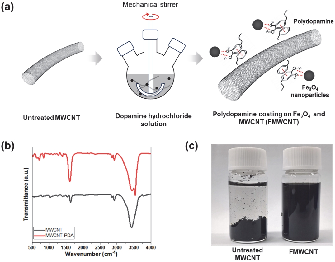
Fig. 2.Characterization of the FMWCNTs: (a–c) SEM images of FMWCNTs synthesized with Fe3O4-to-MWCNT weight ratios of 5, 10, and 15, respectively and (d) VSM magnetization curves of FMWCNTs with different Fe3O4-to-MWCNT weight ratios
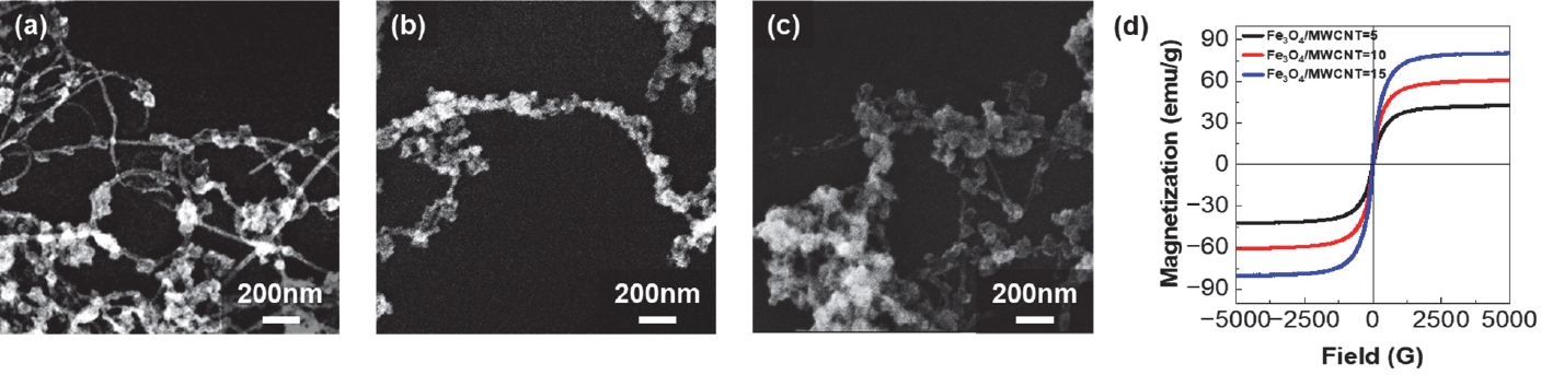
Fig. 3.Magnetic field-induced alignment of the FMWCNTs and the resulting electrical anisotropy: (a) Dark-field optical microscopy images and the corresponding angular distribution histograms of FMWCNT dispersions under applied magnetic field strengths of 0, 10, 50, and 100 mT, (b) Schematic illustration of the electrical percolation pathways in FMWCNT networks oriented parallel and vertical to the electrodes, and (c) current–voltage (I–V) characteristics of the FMWCNT nanocomposites measured in vertical (red), parallel (blue), and random (black) alignments
References
- 1. J. M. Thomassin, C. Jérôme, T. Pardoen, C. Bailly, I. Huynen, and C. Detrembleur, Mater. Sci. Eng. R Rep., 74, 211 (2013). doi: https://doi.org/10.1016/j.mser.2013.06.001
- 2. X. Sun, T. Chen, Z. Yang, and H. Peng, Acc. Chem. Res., 46, 539 (2013). doi: https://doi.org/10.1021/ar300221r
- 3. S. Pujari, S. S. Rahatekar, J. W. Gilman, K. K. Koziol, A. H. Windle, and W. R. Burghardt, J. Chem. Phys., 130, 214903 (2009). doi: https://doi.org/10.1063/1.3139446
- 4. B. W. Steinert and D. R. Dean, Polymer, 50, 898 (2009). doi: https://doi.org/10.1016/j.polymer.2008.11.053
- 5. A. Abdulhameed, Carbon Nanotubes - Recent Advances, New Perspectives and Potential Applications, Chapter 4 (IntechOpen, London, 2022). doi: https://doi.org/10.5772/intechopen.108236
- 6. M. A. Correa-Duarte, M. Grzelczak, V. Salgueiriño-Maceira, M. Giersig, L. M. Liz-Marzán, M. Farle, K. Sierazdki, and R. Diaz, J. Phys. Chem. B, 109, 19060 (2005). doi: https://doi.org/10.1021/jp0544890
- 7. I. T. Kim, A. Tannenbaum, and R. Tannenbaum, Carbon, 49, 54 (2011). doi: https://doi.org/10.1016/j.carbon.2010.08.041
- 8. A. M. Abdalla, S. Ghosh, and I. K. Puri, Diamond Relat. Mater., 66, 90 (2016). doi: https://doi.org/10.1016/j.diamond.2016.04.003
- 9. J. Lee, M. Bak, P. J. Yoo, and W. J. Kim, Appl. Surf. Sci., 688, 162440 (2025). doi: https://doi.org/10.1016/j.apsusc.2025.162440
- 10. J. H. Ryu, P. B. Messersmith, and H. Lee, ACS Appl. Mater. Interfaces, 10, 7523 (2018). doi: https://doi.org/10.1021/acsami.7b19865
- 11. H. Lee, S. M. Dellatore, W. M. Miller, and P. B. Messersmith, Science., 318, 426 (2007). doi: https://doi.org/10.1126/science.1147241
- 12. H. Hemmatpour, O. De Luca, D. Crestani, M. C. A. Stuart, A. Lasorsa, P. C. A. van der Wel, K. Loos, T. Giousis, V. Haddadi-Asl, and P. Rudolf, Nat. Commun., 14, 664 (2023). doi: https://doi.org/10.1038/s41467-023-36303-8
- 13. L. Wu, X. Wu, L. Wu, D. Chen, T. Zhang, H. Zheng, and X. Xiao, ACS Omega., 9, 4949 (2024). doi: https://doi.org/10.1021/acsomega.3c08772
- 14. B. Chen, J. Li, M. Zhang, Z. Dong, and K. Zhang, Compos. Part A Appl. Sci. Manuf., 153, 106709 (2022). doi: https://doi.org/10.1016/j.compositesa.2021.106709
- 15. D. Gim, H. Kwon, and M. Ha, J. Korean Inst. Electr. Electron. Mater. Eng., 38, 89 (2025). doi: https://doi.org/10.4313/JKEM.2025.38.1.12
- 16. V. Ball, D. Del Frari, V. Toniazzo, and D. Ruch, J. Colloid Interface Sci., 386, 366 (2012). doi: https://doi.org/10.1016/j.jcis.2012.07.030
- 17. J. Marroquin, H. J. Kim, D. H. Jung, and K. Y. Rhee, Carbon Lett., 13, 126 (2012). doi: https://doi.org/10.5714/CL.2012.13.2.126