ABSTRACT
This paper proposes a circular sequential lighting control method to reduce current imbalance and luminance deviation among multiple LED modules in AC-powered LED lighting systems. Conventional fixed-sequence lighting control repeatedly prioritizes the same LED modules in every rectified voltage cycle, which leads to unequal current distribution, luminance non-uniformity, and the accelerated degradation of specific modules during long-term operation. To address these limitations, a circular sequential lighting strategy is introduced, in which the lighting order is cyclically rotated at every rectified cycle, ensuring that all LED modules experience equal lighting opportunities. A prototype AC-LED lighting system consisting of four series-connected LED modules was implemented and experimentally evaluated. The results demonstrate that, while the conventional fixed-sequence method produces a maximum average current deviation of up to 1.6 mA among modules, the proposed method equalizes the average current across all modules to approximately 17.1 mA. Furthermore, the flicker index remains at 0.13, which is comparable to that of the conventional method, indicating that luminance uniformity is improved without degradation of optical performance. The proposed circular sequential lighting control effectively distributes electrical stress, enhances luminance uniformity, and improves long-term reliability, making it a practical and efficient solution for high-quality AC-LED lighting applications.
-
KEYWORDS: AC-LED lighting, Circular sequential lighting, Luminance uniformity, Current balancing, Flicker reduction, Multi-module LED systems
1 Introduction
Light-emitting diodes (LEDs) have rapidly replaced conventional incandescent and fluorescent lamps owing to their long lifetime, high luminous efficacy, and environmentally friendly characteristics [
1]. In particular, AC-powered LED lighting systems can directly utilize commercial AC power, enabling simplification of power conversion circuits and reduction in system cost and volume. However, variations in AC input conditions and the intrinsic characteristics of rectified driving introduce several technical challenges that must be addressed.
Key considerations in AC-LED lighting systems include the following. First, variations in the AC input voltage significantly affect LED current and luminance, making stable current regulation essential [
2]. Second, due to the threshold voltage characteristics of LEDs, non-illumination intervals tend to increase in low-voltage regions, leading to optical output fluctuation and increased flicker [
3]. Third, when LED current flows in a stepwise waveform under sinusoidal input voltage, total harmonic distortion (THD) increases; therefore, sinusoidal current control in phase with the input voltage is required [
3–
6]. Fourth, near the zero-crossing region of the input voltage, lighting is limited, resulting in increased percent flicker, necessitating advanced flicker reduction techniques for high-quality lighting applications [
5,
7–
14].
In addition, planar light sources employing multiple LED modules are susceptible to luminance non-uniformity caused by differences in lighting patterns and cumulative operating time among modules. In conventional fixed-sequence lighting schemes, specific modules are repeatedly activated earlier in each cycle, causing uneven current stress and luminance deviation. This not only degrades visual uniformity but also accelerates the aging of certain modules, leading to an imbalance in their operational lifespans.
To overcome these limitations, this study proposes a circular sequential lighting control method that cyclically rotates the lighting priority at each rectified voltage cycle. The proposed approach aims to equalize the current distribution and luminance among all modules. Experimental verification confirms that the proposed method effectively reduces current imbalance and luminance deviation in multi-module AC-LED lighting systems.
2 Experiments
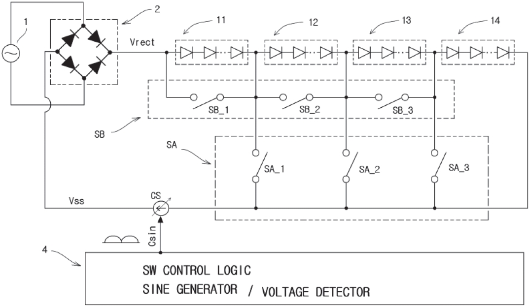
Figure 1 illustrates the configuration of an AC-LED lighting system comprising four series-connected LED modules (11–14).
The system consists of a rectifier that converts the AC input into a rectified voltage, a load stage comprising four series-connected LED modules (11–14), switch blocks (SA, SB) for LED current bypass control, a current source (CS) [
3], and a controller that generates lighting control signals.
The controller produces a sinusoidal reference current (Csin) and detects the instantaneous rectified voltage to determine both the number of illuminated modules and their lighting sequence. By controlling the number of illuminated modules, the equivalent series voltage is adjusted in discrete steps, enabling stable current regulation over the entire input voltage range. This approach ensures sinusoidal input current shaping, reduced THD, and flicker suppression.
3 Results and Discussion
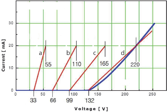
Figure 2 shows the measured current–voltage (I–V) characteristics of the LED emitting modules (11–14) when all modules are connected [
15].
The measured characteristics can be approximated by linear models, allowing analysis of the equivalent series resistance and voltage behavior according to the number of illuminated modules. With both switches (SA, SB) turned off, the characteristic curve can be approximated by line d, where the current is 0 mA at 132 V and reaches approximately 20 mA at 220 V.
When the four modules are evenly divided and selectively illuminated, the equivalent series resistance varies accordingly, producing distinct voltage characteristics for each lighting stage. Line a corresponds to the activation of a single LED module, yielding an equivalent resistance one-fourth that of the full series configuration. Thus, the rated voltage becomes 33 V, and the voltage required to drive 20 mA is approximately 55 V. Line b represents two illuminated modules, yielding 66 V rated voltage and 110 V at 20 mA. Line c corresponds to three modules, yielding 99 V rated voltage and 165 V at 20 mA. Line d corresponds to four illuminated modules.
As the number of illuminated modules increases from one to four, the equivalent series resistance increases stepwise, enabling discrete adjustment of the system voltage and current regulation.
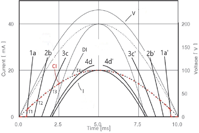
Figure 3 shows the rectified voltage and LED current waveforms measured at a line frequency of 50 Hz and a maximum rectified voltage of 230 V [
15].
The rectified voltage is denoted by V, and the LED current by I. Based on the linear models (a–d), the current waveforms are classified into stages 1a, 2b, 3c, and 4d, corresponding to one-, two-, three-, and four-module illumination.
The design reference current is set as a 20 mA sinusoidal waveform. During intervals T1–T4, the controller regulates the voltage across the current source to ensure the load current follows the reference. In the one-, two-, and three-module illumination stages, continuous lighting of specific modules may cause perceptible luminance differences. Therefore, rapid alternation of illuminated modules—termed circular sequential lighting—is required to achieve uniform brightness perception.
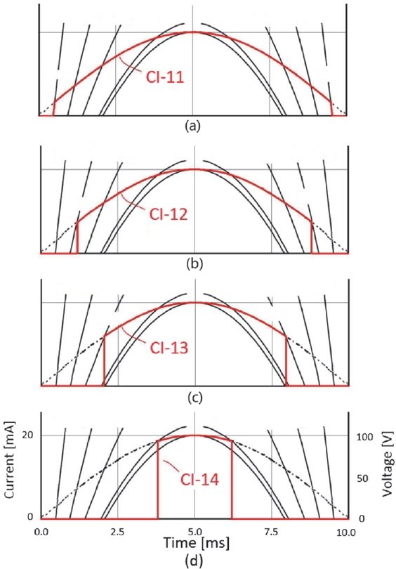
Figure 4 presents the module current waveforms over one rectified cycle using the conventional fixed-sequence lighting control method [
15].
In this scheme, module 11 always participates in the one-, two-, and three-module stages, leading to higher cumulative current stress. The measured average currents are approximately 17.9 mA, 17.6 mA, 17.1 mA, and 16.3 mA for modules 11–14, respectively. This imbalance leads to luminance deviation and accelerates the degradation of specific modules.
To address this issue, a circular sequential lighting method based on a rotate-left operation was applied.
Table 1 summarizes the lighting sequences for four modules.
With the proposed method, the average current of all modules converges to approximately 17.1 mA, and the flicker index remains at 0.13. This confirms that current balancing and luminance uniformity are significantly improved without sacrificing optical quality.
4 Conclusions
This paper proposed a circular sequential lighting control method to mitigate current imbalance and luminance deviation among multiple LED modules in AC-powered LED lighting systems. Conventional fixed-sequence lighting control methods inherently concentrate the lighting duration on specific modules, leading to uneven electrical stress, luminance non-uniformity, and lifetime imbalance.
By rotating the lighting priority at each rectified voltage cycle, the proposed method ensures uniform distribution of lighting time across all modules. Experimental results obtained from a four-module prototype system confirm that the average module current is equalized to approximately 17.1 mA while maintaining a low flicker index of 0.13. These results demonstrate that the proposed approach effectively improves luminance uniformity without degrading optical performance.
In conclusion, the circular sequential lighting control method provides a practical and effective solution for enhancing luminance uniformity, distributing electrical stress, and improving long-term reliability in AC-LED lighting systems. The proposed approach is particularly suitable for high-power and large-area lighting applications requiring high visual quality and operational stability.
Notes
-
Acknowledgement
None.
-
Conflict of Interest
The authors have no conflicts of interest to declare.
-
Author Contributions
Dong Won Lee: Conceptualization, Methodology, Formal analysis, Investigation.
Byungcheul Kim: Formal analysis, Investigation, Writing - Original Draft, Writing - Review & Editing, Visualization, Supervision.
Data Availability
Data not available – participant consent.
Figure 1Configuration of the multi-module AC-LED lighting system
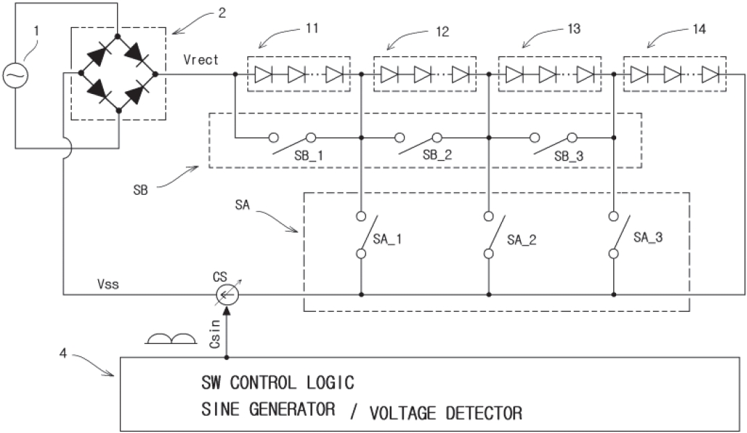
Figure 2Measured current–voltage characteristics of the LED modules
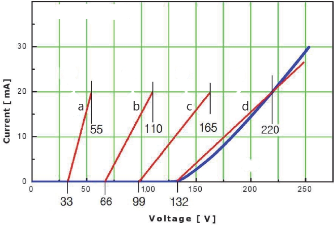
Figure 3Rectified voltage and LED current waveforms at a maximum rectified voltage of 230 V and a line frequency of 50 Hz
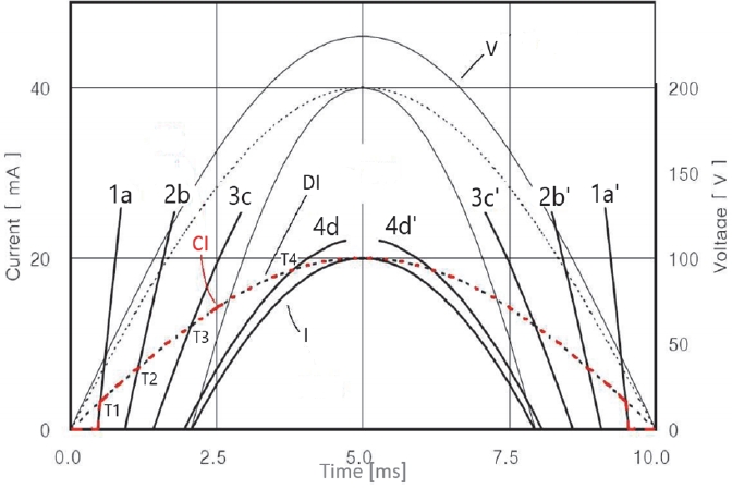
Figure 4Module current waveforms over one rectified-voltage cycle using the fixed-sequence lighting control method: (a) module 11, (b) module 12, (c) module 13, and (d) module 14
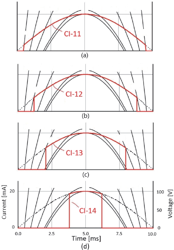
Table 1.Sample classification according to off-axis variation of sapphire substrates
Table 1.
|
Rectification cycle |
1-stage continuous |
2-stage continuous |
3-stage continuous |
4-stage continuous |
|
1 |
11 |
11, 12 |
11, 12, 13 |
11, 12, 13, 14 |
|
2 |
12 |
12, 13 |
12, 13, 14 |
12, 13, 14, 11 |
|
3 |
13 |
13, 14 |
13, 14, 11 |
13, 14, 11, 12 |
|
4 |
14 |
14, 11 |
14, 11, 12 |
14, 11, 12, 13 |
References
- 1. R. Dayal, K. Modepalli, and L. Parsa, In: Proc. 2012 IEEE Energy Conversion Congress and Exposition (ECCE); IEEE. Raleigh, NC, USA. 2012, pp 4230 –4234doi: https://doi.org/10.1109/ECCE.2012.6342248
- 2. D. W. Lee, H. M. An, and B. Kim, J. Korean Inst. Electr. Electron. Mater. Eng., 35, 466 (2022). doi: https://doi.org/10.4313/JKEM.2022.35.5.7
- 3. D. W. L ee, B. H. L ee, and B. Kim, J. Korean Inst. Electr. Electron. Mater. Eng., 36, 255 (2023). doi: https://doi.org/10.4313/JKEM.2023.36.3.7
- 4. K. Seo, V. H. Nguyen, J. Jung, J. Park, and H. Song, IEICE Electron. Express, 11, 20140810 (2014). doi: https://doi.org/10.1587/elex.11.20140810
- 5. J. Kim and S. Park, J. Semicond. Technol. Sci., 15, 390 (2015). doi: https://doi.org/10.5573/JSTS.2015.15.3.390
- 6. K. I. Hwu and W. C. Tu, IEEE Trans. Ind. Informatics, 9, 1330 (2012). doi: https://doi.org/10.1109/TII.2012.2226042
- 7. D. W. Lee, H. M. An, and B. Kim, J. Nanoelectronics Optoelectron., 10, 234 (2015). doi: https://doi.org/10.1166/jno.2015.1737
- 8. K. Örüklü and D. Yıldırım, Eskişehir Tech. Univ. J. Sci. Technol. A Appl. Sci. Eng., 23, 109 (2022). doi: https://doi.org/10.18038/estubtda.978478
- 9. Y. Shen, J. Xia, and C. Cai, World Electr. Veh. J., 14, 75 (2023). doi: https://doi.org/10.3390/wevj14030075
- 10. J. Tan and N. Narendran, J. Light Visual Environ., 38, 6 (2014). doi: https://doi.org/10.2150/jlve.IEIJ130000531
- 11. S. F. Wang, C. M. Kung, Y. C. Yeh, C. R. Lee, and W. T. Tsai, IEEE Access, 11, 97400 (2023). doi: https://doi.org/10.1109/ACCESS.2023.3308197
- 12. P. Fang and Y. F. Liu, IEEE Trans. Power Electron., 32, 3892 (2017). doi: https://doi.org/10.1109/TPEL.2016.2586502
- 13. R. van Roy, Minimizing Light Flicker in LED Lighting Applications Application Note AN022, Richtek, Zhubei City, Hsinchu, Taiwan (2014)
- 14. H. Niu, T. Chen, Z. Hui, C. Geng, T. Song, J. Tao, and S. Xu, IEEE Trans. Electron Devices, 72, 5477 (2025). doi: https://doi.org/10.1109/TED.2025.3601908
- 15. D. W. Lee and B. Kim, J. Electr. Electron. Mater., 39, 193 (2026). doi: https://doi.org/10.4313/JEEM.2026.39.2.8